35 Results
View results:
Sort by:

In this article, you will learn how to model and design cable structures in RFEM 6 or RSTAB 9.

This article describes and explains the influence of bending stiffness of cables on their internal forces. Furthermore, the text provides information on how this influence can be reduced.
,_Table_22.5.5.1_ACI_318-19.png?mw=640&hash=7e50d54e01238943fe1c691c0aa197d9b2fa8511)
With the most recent ACI 318-19 standard, the long-term relationship to determine the concrete shear resistance, Vc, is redefined. With the new method, the member height, the longitudinal reinforcement ratio, and the normal stress now influence the shear strength, Vc. This article describes the shear design updates, and the application is demonstrated with an example.

Using the Concrete Design add-on, concrete column design is possible according to ACI 318-19. The following article will confirm the reinforcement design of the Concrete Design add-on using step-by-step analytical equations as per the ACI 318-19 standard, including the required longitudinal steel reinforcement, gross cross-sectional area, and tie size/spacing.

Steel connections in RFEM 6 are defined as an assembly of components. In the new Steel Joints add-on, universally applicable basic components (plates, welds, auxiliary planes) are available for entering complex connection situations. The methods with which connections can be defined are considered in two previous Knowledge Base articles: “A Novel Approach to Designing Steel Joints in RFEM 6" and “Defining Steel Joint Components Using the Library".

RFEM 6 includes the Form-Finding add-on to determine the equilibrium shapes of surface models subjected to tension and members subjected to axial forces. Activate this add-on in the model's Base Data and use it to find the geometric position in which the prestress of lightweight structures is in equilibrium with the existing boundary conditions.

In RF‑/CONCRETE Columns, different methods are available for defining the minimum longitudinal reinforcement. The minimum reinforcement can be selected according to the design standard used and/or specified by the user.
.png?mw=640&hash=8fd04a597cecae2e434980ce79fc626815a5d98a)
The Aluminum Design Manual (ADM) 2020 was released in February 2020. The ADM 2020 gives guidance for both the allowable strength design (ASD) and load and resistance factor design (LRFD) for aluminum members to ensure reliability and safety for all aluminum structures. This latest standard was integrated in the RFEM/RSTAB add-on module RF-/ALUMINUM ADM. The text below will highlight the applicable updates relevant to the Dlubal programs.

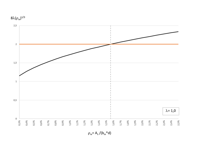
The shear force resistance VRd,c without computational shear force reinforcement according to 6.2.2 of EN 1992-1-1 [1] or 10.3.3 of DIN 1045-1 [2] is calculated depending on the longitudinal reinforcement ratio. If the required longitudinal reinforcement from the bending design is used for the calculation of VRd,c, this leads to an underestimation of the shear force resistance without shear reinforcement in the vicinity of the hinged end supports. In contrast to the shear force, the required bending reinforcement decreases in the direction of the support. Furthermore, the actually inserted longitudinal reinforcement usually deviates significantly from the required bending reinforcement in the end support area (for example, in the case of non-staggered beam reinforcement).
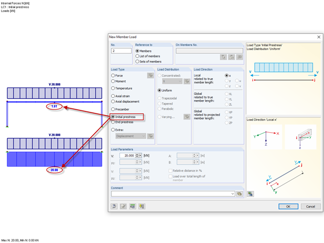
Until now, the prestress load type had always been an initial prestress in Dlubal Software programs. The defined load magnitude was applied and, depending on the stiffness of the surrounding system, prestress remained more or less as an axial force in the cable.
In this article, we will look at the design of shear connectors of cross‑laminated timber structures that transfer the longitudinal forces of the shear wall to the soil.

In Part 1, the selection of the design criteria for dimensioning the reinforcement for the serviceability limit state design in RF‑CONCRETE Members and CONCRETE was explained. Now, we go into detail for the function "Find economical reinforcement for crack width design".
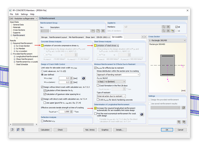
The RF-CONCRETE Members and CONCRETE add-on modules provide the option for "Dimensioning of Longitudinal Reinforcement for Serviceability Limit State". You can select the design criteria for the calculation of the longitudinal reinforcement.
The most recent standard ACI 318‑19 redefines the long-term relation for the determination of the concrete shear resistance Vc. With the new method, the member height, the longitudinal reinforcement ratio, and the normal stress now influence the shear strength, Vc. This article describes the shear design updates, and the application is demonstrated using an example.

Using RF-CONCRETE Members, concrete column design is possible according to ACI 318-14. Accurately designing concrete column shear and longitudinal reinforcement is important for safety considerations. The following article will confirm the reinforcement design in RF-CONCRETE Members using step-by-step analytical equations as per the ACI 318-14 standard, including required longitudinal steel reinforcement, gross cross-sectional area, and tie size/spacing.
Numerous nonlinearities can occur in a structural system. The RF-DYNAM Pro - Nonlinear Time History add-on module was developed in order to model them realistically in a dynamic analysis. To explain how the add-on module works, the procedure is described below with an example.
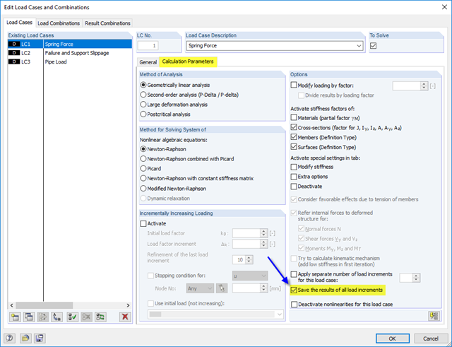
The calculation in RFEM is usually carried out in several calculation steps (iterations). It is then possible to consider particular characteristics of the model, such as objects with nonlinear functions. In addition, by using the iterative calculation, nonlinear effects are taken into account that result from changes in deformation and internal forces in case of the second-order analysis or when considering large deformations (cable theory). In case of complex models, geometric linear calculations are usually insufficient.
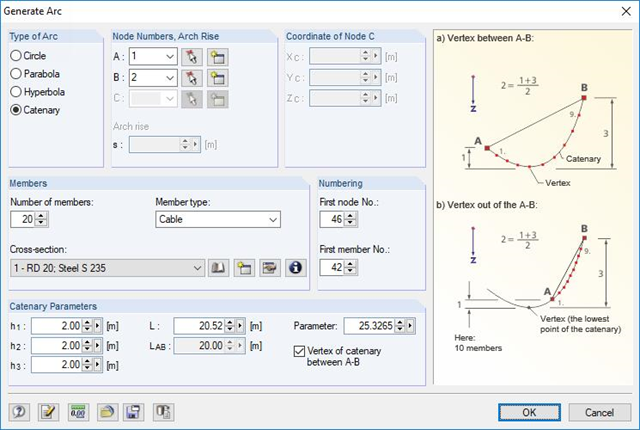
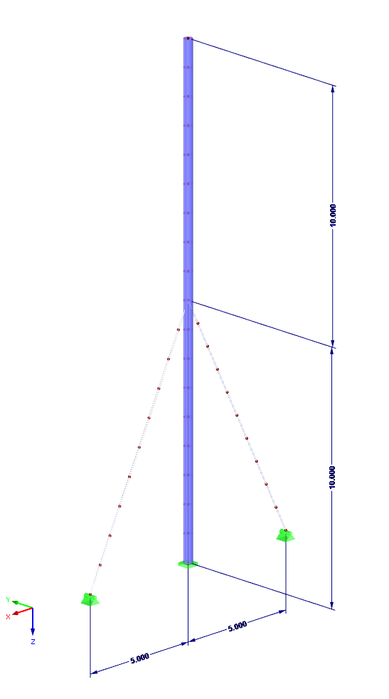
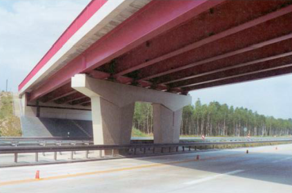
RFEM and RSTAB are able to cover a large number of branches in the building and construction industry with their generally usable structural frame analysis and FEM programs. Designing cable structures is thus also possible in both software solutions. Some assistance tools for modeling and design will be presented in the following text.
.png?mw=640&hash=5852c5c8a1cdb9f021a168d75c0a0466fb430ef7)
Lattice towers represent typical applications in steel construction. Examples of this special type of truss structure are antenna and overhead line towers, as well as columns for wind power stations, cable cars, and supporting frame constructions. The modeling can be done individually in RFEM and RSTAB by entering various tower elements. Furthermore, you can use different copy functions and parameterized input options. However, this procedure normally requires considerable effort. It is more convenient to model such structures using prefabricated catalog elements provided by the Block Manager. These elements are automatically stored in the database during program installation. Thus, you can use tower segments, platforms, antenna brackets, cable ducts, and so on as parameterized building blocks for generating diverse tower structures.
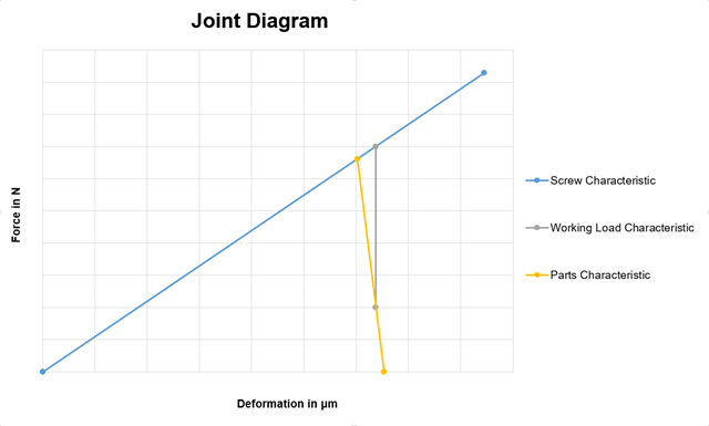
When modeling surface models, such as a frame joint or similar structures, there is always the question of how to model a prestressed bolt connection. In this case, it is always necessary to find a compromise between the practicable and detailed solution. The following article describes the modeling procedure of such a connection, based on the joint diagram calculation method.

Cable and tensile membrane structures are regarded as very slender and aesthetic building structures. The partly very complex double-curved shapes can be found using suitable form-finding algorithms. One possible solution is to search for the form via the equilibrium between the surface stress (provided prestress and an additional load such as self-weight, pressure, and so on) and the given boundary conditions.
![Tension Cover Line from [1]](/en/webimage/009390/2418541/01-en-png.png?mw=640&hash=c76563b459152b19c98197ea6ba342be89d9a5bc)
In the case of a large amount of reinforcement, it might be useful to grade the longitudinal reinforcement of a beam, which means: curtailment. The grading corresponds to the tensile force distribution. Using RF-CONCRETE Members and CONCRETE, you can specify the curtailment of the reinforcement, which is considered in the automatically proposed reinforcement for the longitudinal reinforcement. When determining this reinforcement proposal, it is necessary to ensure that the envelope of the acting tensile force can be absorbed.
![Design Model for Bonded Joint Resistance According to [1]](/en/webimage/009526/2419234/01-en-png.png?mw=640&hash=c76563b459152b19c98197ea6ba342be89d9a5bc)
In the construction process, it is often necessary to fabricate the concrete elements in sections. A classic example of this production in sections is the use of prefabricated downstand beams, in which the slab is completed in the onsite concrete construction. By creating a new concrete area, interfaces may arise between the already hardened concrete and the fresh concrete. The transfer of the longitudinal shear forces arising between the partial cross-sections must be considered in the design.
Composite beams in a three-dimensional analysis are usually connected with orthotropic plates. In that case, the longitudinal direction of the plate stiffness is defined by a main beam and the transverse direction by an orthotropic plate. The stiffness of the plate in the longitudinal direction is set almost to zero. This article explains the determination of stiffnesses in the orthotropic plate.
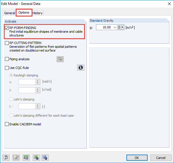
The RF-FORM-FINDING add-on module determines equilibrium shapes of membrane and cable elements in RFEM. In this calculation process, the program searches for such geometric position where the surface stress/prestress of membranes and cables is in equilibrium with natural and geometric boundary conditions. This process is called form-finding (hereinafter referred to as FF). The FF calculation can be activated in RFEM globally in the "General Data" of a model, "Options" tab. After selecting the corresponding option, a new load case or a calculation process called RF-FORM-FINDING is created in RFEM. An additional FF parameter is available for defining surface stress and prestress when entering cables and membranes. By activating the FF option, the program always starts the form-finding process before the pure structural calculation of internal forces, deformation, eigenvalues, etc., and generates a corresponding prestressed model for further analysis.
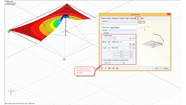
The form-finding process in RFEM seeks an equilibrium state where the defined prestress of membranes and the prestress or length changes of cable elements with boundary reactions are in equilibrium. For this, the program provides the option to define an isotropic or an orthotropic prestress state for membranes.
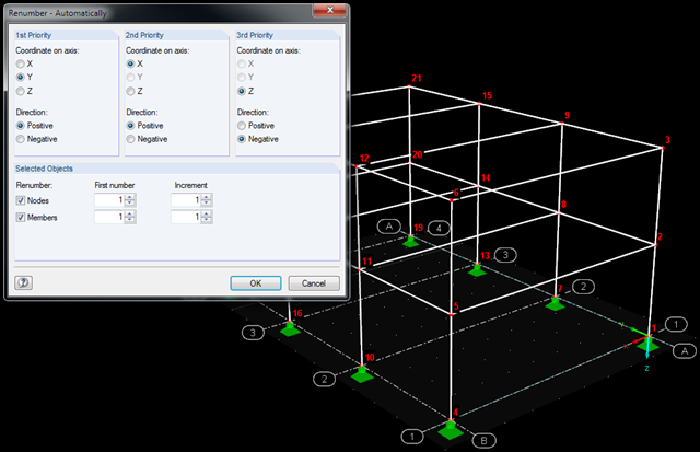
When modeling a structure, irregular numbering of objects may occur due to copying, dividing lines and members, and so on. Automatic renumbering allows you to restructure the numbering and thus to improve the clear arrangement. This function is applicable to nodes and members as well as for lines, surfaces, and solids in RFEM.
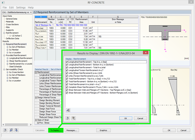
Using the [To Display…] button, you can specify the amount of reinforcement to be displayed in the results of the required reinforcement in Window 2.2 of RF‑CONCRETE and CONCRETE. In addition to the default setting, you can display the resulting reinforcement amount as (for example) the sum of the longitudinal and longitudinal torsion reinforcement, or the sum of the torsion and shear reinforcement. You can also reduce the number of preset results, of course.

Torsional buckling analysis of transverse and longitudinal stiffeners with open cross-sections is described in DIN EN 1993-1-5, Chapter 9. There is a difference between the simplified method and the precise method, which takes into consideration the warping stiffness of the buckling panel. The simplified method applies Equation 9.3 of DIN EN 1993‑1‑5. If warping stiffness is to be taken into account, either Eq. 9.3 or Eq. 9.4 should be followed. Both design methods are implemented in PLATE-BUCKLING.
In addition to bending, torsional, longitudinal, and strain loads, you can define and analyze the internal pressure of members with circular hollow cross‑sections in RFEM and RSTAB. The following perimeter and axial stresses resulting from the internal pressure load are analyzed using Barlow's formula and transferred to design modules in order to superimpose the remaining stresses due to internal forces.